


ME-35
Applicable motor: 3525、3530、3540、528、385、395
Magnet poles: 13PPR
Magnet size: Φ 14X Φ 2X2mm Φ 14X Φ 2.3X2mm
- 产品描述
- 产品参数
-
- Commodity name: ME-35
- Commodity ID: 1016357789183598592
DM-ME-35
Applicable motor: 3525、3530、3540、528、385、395
Magnet poles: 13PPR
Magnet size: Φ 14X Φ 2X2mm Φ 14X Φ 2.3X2mm
Key words:- DM-ME-35
-
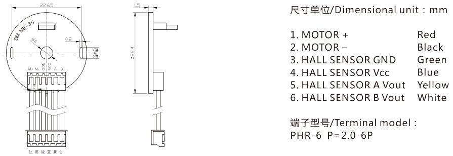
Product Dimensions(unit:mm):
Electrical Characteristics:
Characteristics Symbol
Test Conditions Values Unit Min. Typ. Max. V Supply Voltage VS Operating 3.0 5 18 V Output Voltage VQ - - 18 V Temperature Tj -40 - 150 ℃ Output Current IQ - - 50 mA Supply Current IS B < Brp - 4 6 mA Reverse Battery Current Vrcc - - -0.5 V Output Saturation Voltage VQSAT Iout = 10 mA,B > Bop - 0.25 5 V Output Leakage Current IQLEAK B < Brp , Vout = 18V - 0.1 1 µA Output Fall Time tf RL = 10 kΩ
CL = 20 pF
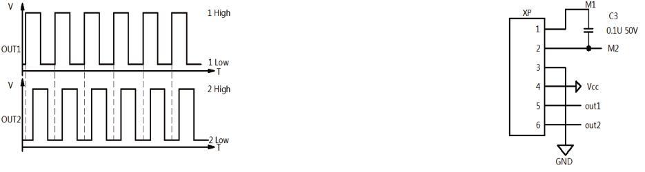
- - 1 µS Output Rise Time tr - - 1 µS Waveform:
Using the Encoder:
A two-channel Hall effect encoder is used to sense the rotation of a magnetic disk on a rear protrusion of the motor shaft. The encoder board senses the rotation of the magnetic disc and provides a resolution of 52 counts per revolution of the motor shaft when counting both edges of both channels. To compute the counts per revolution of the gearbox output shaft, multiply the gear ratio by 52.
The hall sensors are powered through the VCC and GND pins. VCC can be 3.0 V to 18 V, and the quadrature outputs A and B are digital signals that are either driven low (0 V) by the sensors or pulled to VCC through 10 kΩ pull-up resistors,depending on the applied magnetic field.The A and B outputs are square waves approximately 90° out of phase. The sensors' comparators have built-in hysteresis, which prevents spurious signals in cases where the motor stops near a transition point.The frequency of the transitions tells you the speed of the motor, and the order of the transitions tells you the direction.
By counting both the rising and falling edges of both the A and B outputs, it is possible to get 52 counts per revolution of the motor shaft. If using just a single edge of one channel (A or B)results in 13 counts per revolution of the motor shaft.
Recommended Products
Tell us About Your Project Requirements
Powered www.300.cn SEO
Email: sales@dmdcmotor.com
We will give you feedback in time